Electric motor test stands are engineered validation systems used to measure, load, control, and qualify electric motors under repeatable operating conditions. For defense applications, these systems support propulsion motors, actuators, generators, pumps, fans, and drive assemblies across UAVs, ground vehicles, naval platforms, and aerospace systems.
This page showcases leading electric motor test stand suppliers, with solutions for torque, speed, efficiency, thermal, vibration, endurance, fault, and dynamic response testing under representative duty cycles.
If you design, build or supply Electric Motor Test Stands, create a profile to showcase your capabilities and connect with visitors who have an active requirement for your solutions.
Overview of Electric Motor Test Stands for Precise Thrust Measurement
Overview by
William Mackenzie
Updated:
Introduction to Electric Motor Test Stands
An electric motor test stand is a highly engineered system used to measure, load, control, and validate electric motors under repeatable conditions. In defense engineering, motor test stands serve as critical risk-reduction tools used to qualify propulsion motors, actuators, generators, pumps, fans, and drive systems before integration into mission-critical tactical platforms.
As electric and hybrid-electric architectures expand across unmanned systems, military ground vehicles, naval platforms, and aerospace applications, comprehensive motor testing has become central to system assurance. A motor that performs well during an isolated no-load bench test can behave unpredictably when subjected to inverter switching harmonics, thermal soak, high vibration, altitude effects, restricted cooling, or demanding military duty cycles. The right motor test stand exposes these issues early, quantifies performance, and provides empirical evidence for design, acceptance, qualification, and sustainment decisions.
Core Functions of an Electric Motor Test Stand
The foundational objective of an electric motor test stand is to translate physical operation into high-fidelity engineering data while supporting platform safety, repeatability, and compliance.
Mechanical and Electrical Performance Mapping
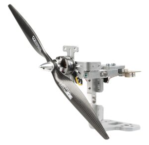
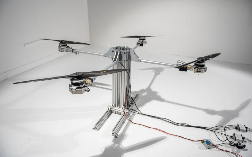
Electric Motor and Thrust Test Stand by Tyto Robotics
Accurate torque and speed measurements allow defense engineers to map torque-speed curves, identify peak operating regions, validate motor controller current limits, and support analytical simulation models. Measuring mechanical shaft output alongside electrical inputs, such as DC bus voltage and current, inverter phase voltage and current, voltage ripple, phase balance, harmonic content, and AC input power factor where applicable, provides the synchronization needed to map efficiency contours.
This dual-sided characterization helps prevent marginal powertrain efficiency losses from escalating into range penalties for Unmanned Aerial Vehicles (UAVs). It also verifies that the system can tolerate platform power networks that may encounter voltage transients, surges, dropouts, and other power-quality disturbances.
Environmental, Thermal, and Structural Health Monitoring
A professional motor test stand validates thermal margins by measuring or estimating winding temperatures, monitoring stator casing temperatures, and tracking coolant temperatures where liquid cooling is used. These measurements support steady-state and transient tests designed to prevent insulation degradation or permanent magnet demagnetization caused by resistive and core losses.
The stand may also integrate accelerometers, acoustic sensors, proximity probes, or other condition-monitoring instrumentation to capture signatures linked to dynamic imbalance, bearing degradation, or structural resonance. Managing these thermal and vibration profiles is especially important for reconnaissance drones and low-signature platforms, where excessive heat, vibration, or acoustic output can affect sensor stability, reliability, and detectability.
Dynamic Transients, Life Cycle Endurance, and Fault Verification
Dynamic testing evaluates closed-loop control stability, torque responsiveness, latency, and overshoot of the integrated motor and drive system during rapid step changes, emergency stops, drone maneuvers, or missile fin actuator reversals. Endurance profiles may run for hundreds or thousands of hours to map long-term wear, insulation breakdown, and bearing grease degradation.
The stand can also introduce controlled failure modes such as phase loss, sensor dropout, cooling-flow interruption, and bus overvoltage transients within a protected environment. This helps prove that a motor and controller can transition safely into a benign state during an anomaly, flag diagnostic codes to the vehicle bus, and reduce the risk of cascading failures.
Main Types of Electric Motor Test Stands
The architecture of a test stand varies based on motor topology, power envelope, operating speed, loading method, and qualification requirements.
Dynamometer and Regenerative Test Systems
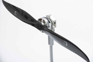
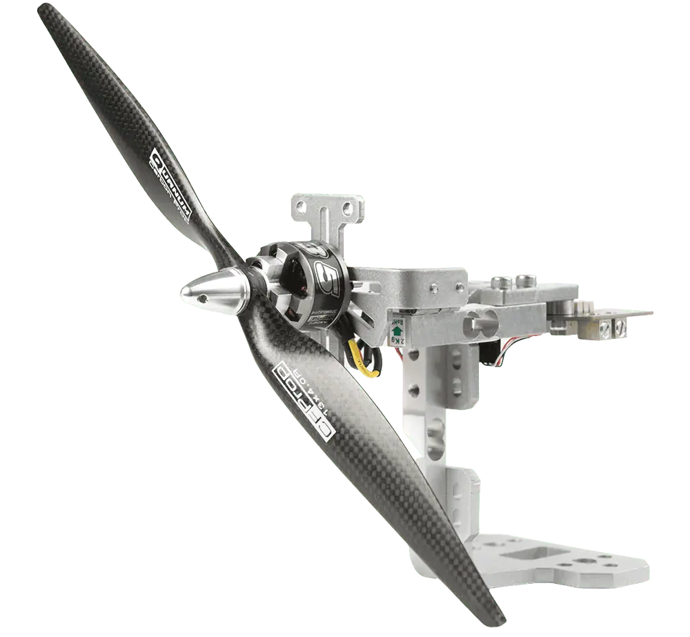
Thrust Test Stand by Tyto Robotics
Dynamometer systems map mechanical performance by using an AC or DC motoring dynamometer, eddy-current brake, magnetic particle brake, or high-speed hysteresis brake as a controllable mechanical load. These systems may also serve as DC motor testing equipment for brushed or brushless DC motor validation, depending on the drive architecture and instrumentation.
For high-power applications, regenerative test stands capture mechanical energy from the load machine and, where configured for regeneration, feed it back into the facility’s AC grid or a shared DC bus. This can reduce electrical consumption and thermal rejection while enabling bidirectional testing of motoring efficiency and regenerative braking dynamics in heavy vehicle drivetrains and hybrid-propulsion systems.
Loaded, No-Load, and Specialty Aerodynamic Thrust Stands
No-load test benches are useful for rapid screening, incoming quality control, and depot-level maintenance validation by checking rotational direction, phase commutation, and back-EMF constants. However, no-load testing cannot validate thermal margins under load, magnetic saturation limits, or true efficiency maps, so loaded test benches remain essential for flight-critical military hardware.
For small Unmanned Aerial Systems (sUAS) and loitering munitions, a brushless motor test stand or brushless motor thrust stand applies an aerodynamic propeller load and combines electrical measurements with propulsion data. Depending on configuration, the same system may be described as a drone motor test bench, drone motor test stand, drone thrust stand, drone test stand, drone motor thrust stand, thrust stand for drone propulsion, thrust measuring stand, or motor thrust stand. These rigs may incorporate multi-axis load cells to isolate real-time propeller thrust, motor torque, and structural reaction forces during a propeller thrust test, mapping electrical input directly to mechanical thrust output.
High-Speed, High-Torque, and Environmental Chambers
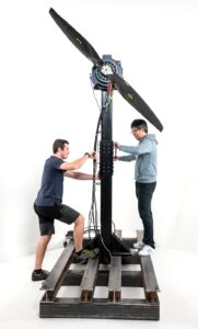
High-speed rigs are engineered for high-RPM applications such as UAV propulsion or compact compressors, requiring precise dynamic balancing, high-frequency data acquisition, and safety shielding to protect operators from rotor failure or blade delamination. High-torque stands validate traction systems, turret drives, winches, and launch mechanisms where extreme rotational force dominates, requiring structural bedplates and torsionally stiff couplings for sustained stall-torque conditions and rapid reversals.
When environmental validation is required, environmental motor test chambers place the motor, and in some configurations the loading mechanism, inside a controlled climate enclosure. This allows engineers to evaluate performance across temperature cycling, humidity, sand and dust exposure, salt fog exposure, and low-pressure altitude simulation as defined by the qualification plan and MIL-STD-810 tailoring.
Control Software & Automation
Modern electric motor testing relies on software-defined automation to improve repeatability, safety, and data quality.
Test Sequencing and Automated Profile Execution: Software automation runs multi-hour scripts from pre-test continuity checks to controlled cooldown sequences, reducing operator variance.
Closed-Loop Real-Time Control: High-speed algorithms govern speed, torque, electrical current, and temperature control loops where supported by the test architecture.
Real-Time Monitoring and Limit Enforcement: Control software checks incoming data against safety thresholds, with independent hardware protection used where required for immediate shutdown.
Fault Injection and Verification: Rigs can introduce controlled anomalies such as encoder dropouts, phase-loss conditions, simulated short-circuit faults, cooling-flow interruptions, or bus-voltage transients to verify controller response.
Configuration Management and Traceability: Secure recipe management systems can link raw time-series data to asset serial numbers, calibration records, software versions, and firmware hashes to create a controlled audit trail.
These software layers transform the physical test stand into an automated validation environment capable of supporting stringent military criteria.
Standards, Compliance & Qualification
Compliance with international and military standards provides a shared engineering language that helps ensure test data is valid, repeatable, and defensible during defense acquisition reviews.
The IEC 60034 Series and Efficiency Measurement: Industrial standards establish baseline performance ratings, while laboratory methodologies isolate internal machine losses to reduce instrumentation errors in power budget calculations.
MIL-STD-810 Environmental Tailoring: This framework provides environmental engineering guidance and test methods that may require powered or operational testing under representative load during conditions such as temperature extremes, low pressure, humidity, sand, dust, or salt fog, depending on the platform and qualification plan.
MIL-STD-461 Electromagnetic Compatibility (EMC): Test rigs must control grounding, shielding, cabling, ambient emissions, and support-equipment coupling so conducted and radiated emissions from the motor drive can be measured accurately.
MIL-STD-704 and MIL-STD-1275 Input Power Quality: Test stands can integrate programmable power supplies, regenerative DC sources, or transient-generation equipment to simulate aircraft power characteristics and ground vehicle voltage disturbances.
ISO/IEC 17025 Laboratory Competence: This standard demonstrates laboratory competence for testing and calibration, supporting traceable measurements, documented uncertainty budgets, and defensible results for high-consequence defense programs.
Adhering to these criteria helps ensure that fielded components have been vetted against relevant operational environments and qualification requirements.
Emerging Trends in Electric Motor Testing
As defense organizations accelerate electrification, push power densities higher, and integrate autonomous capabilities, electric motor testing is moving from simple measurement benches toward integrated digital engineering assets.
High-Voltage Architecture Validation: Test stands are adapting to 400 VDC to 800 VDC architectures by using isolated sensors, active insulation monitoring, and high-bandwidth instrumentation.
Integrated Multi-Physics Testing: Advanced rigs combine load application, climate chambers, vibration tables, and EMI shielding to capture simultaneous environmental and operational stresses.
Automated Digital Evidence Packs: Automated workflows can tie raw data logs to asset serial numbers, calibration records, software versions, and firmware hashes for design reviews and configuration auditing.
Autonomy Integration and Prognostic Verification: Modern infrastructure can introduce controlled degradation over time to verify that onboard health management algorithms can detect faults and adapt mission profiles safely.
These practices help testing methodologies keep pace with modern unmanned and hybrid combat platforms.
Tyto Robotics explores electromagnetic interference challenges in drone propulsion testing and outlines practical techniques to improve reliability and measurement accuracy
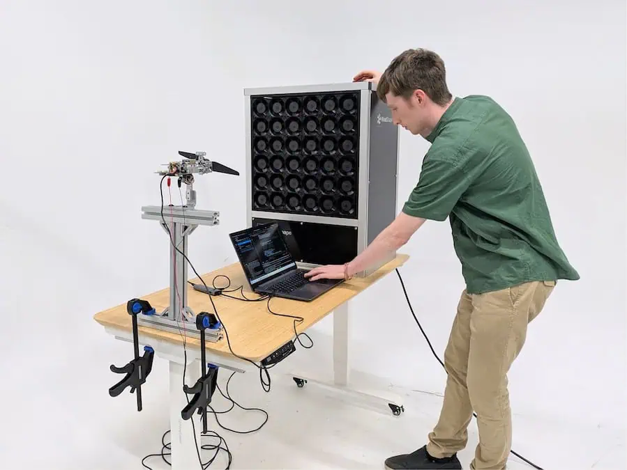
Tyto Robotics has partnered with WindShape in a five-year agreement to expand access to UAV testing solutions worldwide through integrated equipment, training resources, and a global distribution network
Tyto Robotics compares its Flight Stand with other thrust stands, showing its precision, stability, and advanced features for defense and aerospace propulsion testing
Tyto Robotics explains how its DEP testing platform evaluates distributed electric propulsion systems, analyzing up to eight powertrains simultaneously to optimize efficiency, reliability, and safety
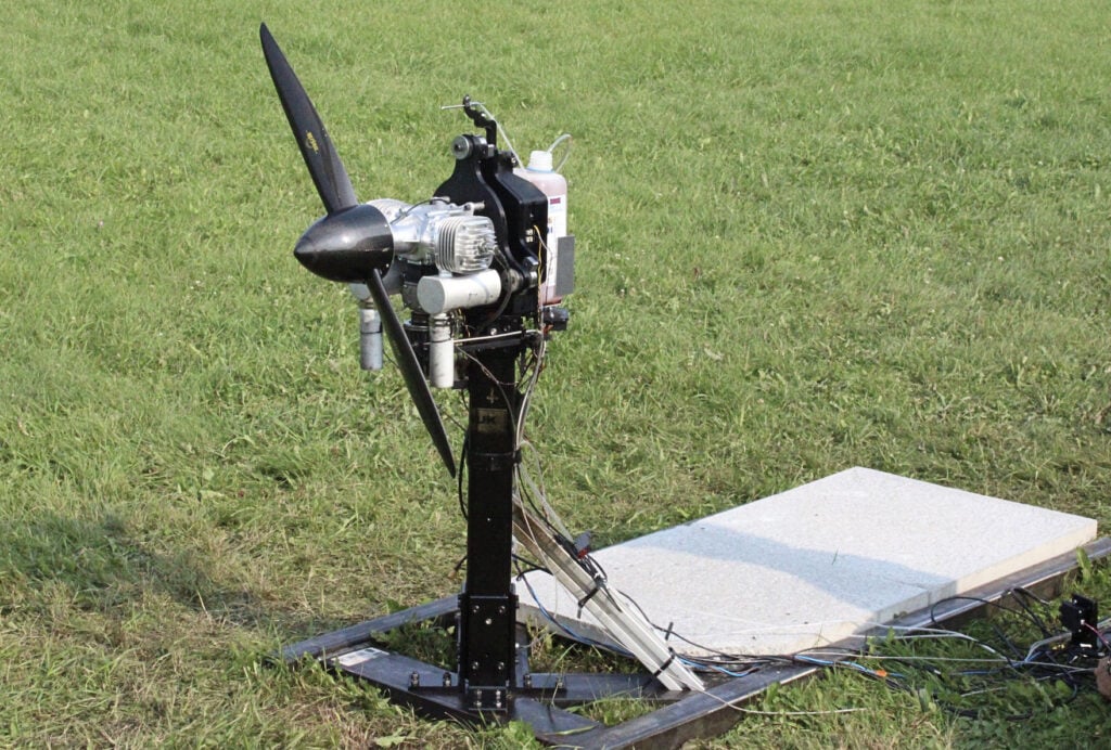
The Flight Stand 60 Engine Test Stand by Tyto Robotics offers a precise, versatile solution for testing internal combustion engines and propellers, providing detailed performance measurements and optimization capabilities
Tyto Robotics highlights 21 practical methods for extending UAV flight times and improving airborne performance, ideal for both custom and ready-to-fly systems
Tyto Robotics has conducted a comprehensive study on dual motor and coaxial propulsion systems for drones, utilizing Flight Stand 50 thrust stands to measure key outputs
Nov 06, 2024
Advancing Defense Capability Through Strategic Collaboration
Defense Advancement works with major OEMs to foster collaboration and increase engagement with SMEs, to accelerate innovation and drive defense capabilities forward.