Showcase your capabilities
If you design, build or supply AESA Radar, create a profile to showcase your capabilities and connect with visitors who have an active requirement for your solutions.


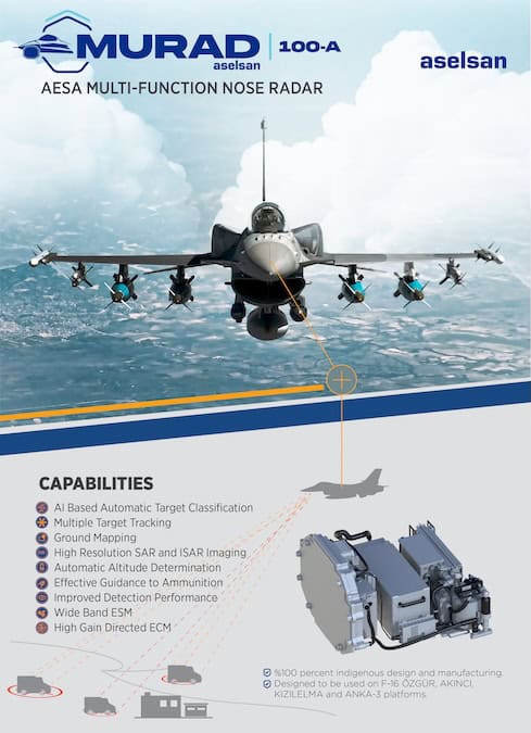
AESA radar systems are Active Electronically Scanned Array sensors that use distributed transmit/receive modules to steer RF energy electronically without mechanically moving the antenna. Designed for military and defense applications, radar AESA solutions support combat aircraft, naval systems, ground-based air defense, counter-UAS platforms, ISR payloads, and integrated air and missile defense networks.
This page showcases AESA radar manufacturers offering active electronically scanned array systems for rapid target acquisition, multi-mode operation, track-while-scan, SAR/GMTI mapping, and electronic warfare support, with ruggedized, SWaP-C-conscious designs engineered for demanding operational environments.
Read the Technology Overview

Radar Reinvented: Radars for Counter-UAS, Base & Asset Security, and Portable ISR
If you design, build or supply AESA Radar, create a profile to showcase your capabilities and connect with visitors who have an active requirement for your solutions.

Active Electronically Scanned Array (AESA) radar systems offer faster target acquisition, interleaved multi-mode operation, and greater tracking precision for military and defense applications.
Unlike legacy mechanically scanned radars that physically rotate antenna assemblies to direct radio frequency (RF) energy toward a target, an active electronically scanned array radar manipulates the phase and timing of signals across an array of hundreds or thousands of independent miniature antennas. This architectural shift from mechanical steering to solid-state electronic beam steering allows a modern system to redirect radar energy almost instantaneously.
AESA radar technology also differs from Passive Electronically Scanned Arrays (PESA), which utilize a single, centralized RF source routed through variable phase shifters. An AESA radar system distributes both the transmitter and receiver functionality directly across the face of the antenna array. This technology has been adopted for a wide range of use cases including fifth-generation combat aircraft, integrated air and missile defense networks, naval combat systems, counter-UAS platforms, and advanced intelligence, surveillance, and reconnaissance (ISR) payloads.
The core operational advantage of an electronically scanned array radar rests on its distributed architecture. Instead of generating a single, high-power radar beam from a central vacuum-tube transmitter (such as a traveling-wave tube), an AESA radar system relies on an array of independent, solid-state Transmit/Receive (T/R) modules.
Each individual T/R module is essentially a self-contained, miniature radar terminal. A typical module integrates several critical components:
By precisely shifting the phase of the RF signal emitted from each module, the radar creates constructive interference patterns in specific directions, shaping and steering highly directional beams within microseconds.
Early generation AESA systems relied on Gallium Arsenide (GaAs) technology. While revolutionary at the time, GaAs-based systems are rapidly being superseded by Gallium Nitride (GaN) semiconductor architectures.
Architectural Systems and Digital Beamforming (DBF)
Modern high-performance AESA radars rely on a balance of RF front-end capability and digital back-end processing.
Legacy systems relied purely on analog phase shifting behind the antenna face. Next-generation AESA radar technology increasingly moves the analog-to-digital converter (ADC) and digital-to-analog converter (DAC) closer to the individual element level. This approach enables Digital Beamforming (DBF).
Instead of combining all received signals into a single analog channel, DBF architectures digitize the returns at the subarray or individual module level. This preserves the complete spatial and phase information of the incoming wavefront, allowing the radar computer to synthesize multiple independent, simultaneous tracking and search beams from a single aperture. DBF also enables highly advanced spatial filtering, allowing the radar to place precise, deep nulls in the antenna’s directional pattern to completely suppress enemy jammers.
Processing the immense data pipelines generated by digital beamforming requires massive computational bandwidth at the tactical edge. Modern AESA processing architectures rely on heterogeneous computing blocks, including:
To mitigate obsolescence and reduce lifetime sustainment costs, contemporary defense acquisition mandates hardware and software alignment with Modular Open Systems Approaches (MOSA). Hardware integration increasingly relies on standard form factors like OpenVPX, adhering to standards defined by the Sensor Open Systems Architecture (SOSA) consortium. This approach ensures that individual processing cards, exciters, or RF modules can be upgraded incrementally without necessitating a complete redesign of the radar’s foundational architecture.
The operational deployment of an AESAradar dictates its specific frequency band selection, as the physics of electromagnetic propagation force a trade-off between detection range, tracking resolution, and physical package size.
Operating effectively within congested or highly contested environments requires advanced signal processing to filter out unwanted reflections from land, sea, and precipitation. AESA radars utilize high pulse-repetition frequency (PRF) Doppler filtering and adaptive space-time adaptive processing (STAP) algorithms to isolate moving targets out of severe ground or sea clutter.
Furthermore, defeating low-observable (stealth) targets requires a combination of high receiver sensitivity, extreme waveform diversity, and advanced tracking filters that can pull micro-signals out of the background noise floor by correlating subtle target returns over time.
The true operational strength of an AESA system is its ability to eliminate the historical boundary between dedicated search radars, fire control radars, and electronic warfare systems. By dividing the array face dynamically, a single AESA radar can simultaneously run multiple operational modes.
In air-to-air applications, an AESA radar can conduct continuous volume search across a wide volume of space while maintaining high-priority, high-update-rate tracks on multiple separate airborne threats. This Track-While-Scan (TWS) agility allows the launch and simultaneous guidance of multiple beyond-visual-range (BVR) missiles.
Simultaneously, the system can interleave air-to-surface modes. By utilizing Synthetic Aperture Radar (SAR) processing, the radar can generate photographic-quality ground maps through cloud cover, smoke, and adverse weather conditions. These maps can be overlaid with Ground Moving Target Indication (GMTI) data, highlighting moving vehicular targets against a static background map for immediate targeting.
Because each T/R module is fully programmable and frequency-agile, an active electronically scanned array can quickly pivot from a sensing role to an electronic warfare asset.
Traditional radars act like flashlights in a dark room, exposing their own location the moment they turn on. AESA systems mitigate this vulnerability through advanced LPI waveforms. By spreading transmission energy across a broad frequency band via high-speed frequency hopping, using pseudo-random noise codes, and dynamically reducing output power to the absolute minimum needed to maintain a track, an AESA radar can blend into the natural background electromagnetic noise. Enemy radar warning receivers (RWRs) struggle to isolate, recognize, or geolocate these spread-spectrum transmissions.
Engineering a high-performance active electronically scanned array radar requires overcoming intense Size, Weight, Power, and Cost (SWaP-C) constraints, particularly when tailoring systems for demanding military environments.
Because GaN and GaAs components are solid-state, their operational lifespan, reliability, and RF performance degrade if junction temperatures exceed strict limits. Since thousands of modules are packed tightly together, managing waste heat is a primary engineering concern.
AESA arrays must maintain sub-millimeter structural alignment across extreme operating envelopes to prevent phase errors from degrading the beam profile.
Every AESA radar deployed on modern defense platforms must undergo rigorous testing regimes to meet strict international military and aerospace standards, which may include.
As defense capabilities shift toward highly distributed, multi-domain operations, new innovations in AESA technology are being developed to match.
Traditional radar resource management relies on pre-programmed scheduling algorithms. Next-generation cognitive radar integrates machine learning loops directly into the signal processing pipeline. By evaluating the real-time return signals and the electromagnetic environment, a cognitive AESA can autonomously alter its waveform, adaptive frequency selection, pulse repetition frequency, and look-schedule to defeat complex, adaptive electronic jamming threats on the fly.
Rather than relying solely on a single, high-output nose or mast sensor, future tactics emphasize distributed sensing. Using highly synchronized clocks, a single platform may split its radar functions across multiple smaller conformal arrays wrapped around the fuselage or hull of a platform, providing continuous 360-degree coverage without blind spots.
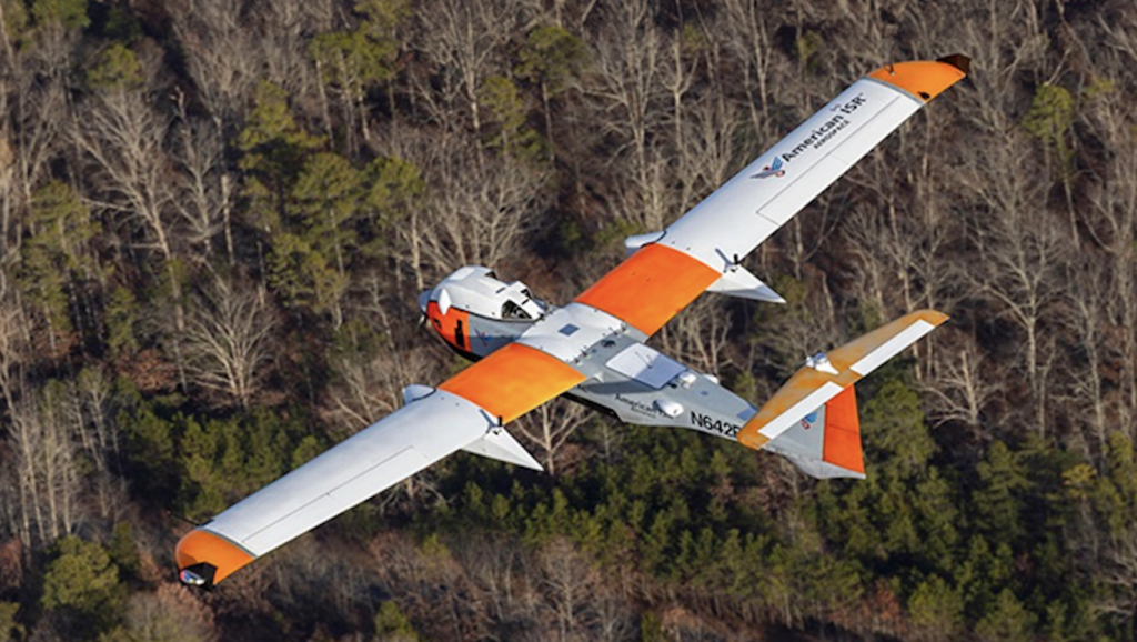
Furthermore, in multi-static radar configurations, one asset (such as a stealthy unmanned aerial vehicle) can fly passively without emitting any RF signatures, while capturing the bistatic reflections generated by a distant, high-power AESA radar located safely on a non-stealthy rear-echelon platform.
The rise of hypersonic cruise missiles and glide vehicles travelling at speeds greater than Mach 5 presents a critical challenge to traditional radar networks. The extremely fast update rates, microsecond beam positioning, and high-frequency Doppler processing native to modern GaN-based AESA radars are foundational to detecting, tracking, and engaging these ultra-high-velocity threats before they penetrate close-in defense perimeters.


 Searching Companies & Products


 Subscribe to the Weekly eBrief
The latest engineering and technical developments straight to your inbox - join thousands of engineers who receive it.
Subscribe to the Weekly eBrief
The latest engineering and technical developments straight to your inbox - join thousands of engineers who receive it.