
Showcase your capabilities
If you design, build or supply RF Upconverters, create a profile to showcase your capabilities and connect with visitors who have an active requirement for your solutions.



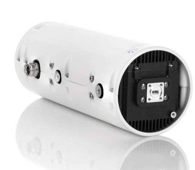
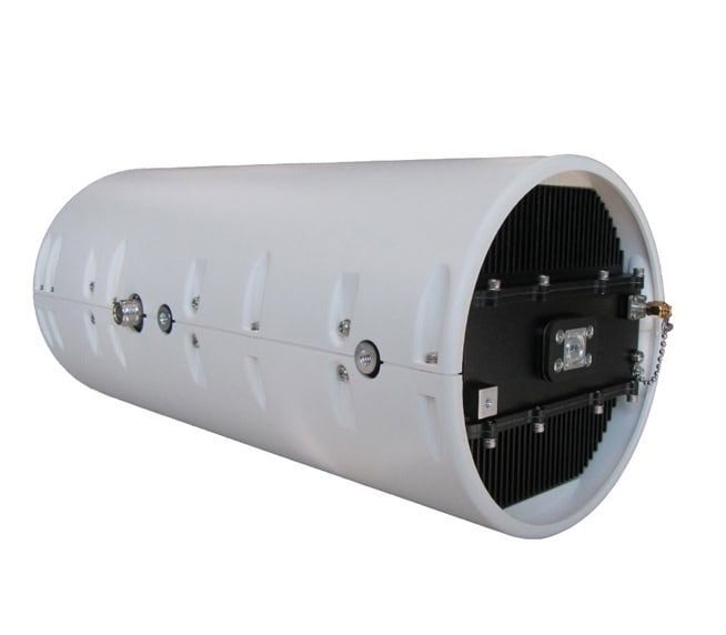
RF upconverters are SATCOM transmit-chain components that translate modem IF or L-band signals into higher RF uplink frequencies for defense satellite communications. These systems include dedicated IF-to-RF converters, L-band converters, and block upconverters (BUCs) that combine frequency conversion with power amplification in antenna-mounted modules.
This page showcases leading RF upconverter suppliers and BUC manufacturers supporting tactical SATCOM, across C, X, Ku, Ka frequency bands.
Read the Technology Overview

High-Powered Microwave & RF Solutions for Mission-Critical Military & Defense Applications

If you design, build or supply RF Upconverters, create a profile to showcase your capabilities and connect with visitors who have an active requirement for your solutions.

RF frequency upconverters and block upconverters (BUCs) serve as the fundamental bridge between the modem’s IF or L-band output and the satellite uplink RF chain in defense SATCOM networks. Operating as an IF to RF upconverter or L-band to RF converter, their primary role is translating a lower intermediate frequency or L-band signal from a modem into a higher radio frequency for satellite uplink. In tactical setups, a block upconverter integrates frequency conversion and power amplification into a single antenna-mounted unit to minimize waveguide loss and simplify integration. To maintain frequency precision under harsh environmental stress, many systems utilize phase-locked local oscillators tied to an external 10 MHz reference.
Distinguishing a dedicated upconverter or SATCOM BUC from standalone RF amplifiers, Solid-State Power Amplifiers (SSPAs), or full transceivers is critical for military procurement. An upconverter handles frequency translation exclusively, while an amplifier solely boosts raw signal power, and an SSPA elevates wattage once the signal is already at its final RF frequency. A satellite BUC combines frequency translation and power amplification into one module. Transceivers represent a broader architecture, incorporating both the transmit and receive paths and often including monitoring and control functions to help manage the link.
Deployed forces rely on tactical SATCOM to transmit high-definition video, voice, and command data across distances that traditional line-of-sight radios cannot bridge. A BUC in satellite communications functions as the active heart of this uplink path, translating the terminal’s native IF signal and supplying the RF output power required to meet the link budget. Operationally, the performance of the satellite BUC is a major factor in maintaining viable uplink margin during severe weather, long slant ranges, or antenna tracking errors.
Mobile command elements require communication infrastructure that can be quickly transported, assembled, and run in unpredictable field environments. Flyaway and vehicle-mounted terminals typically fix the block upconverter modules directly onto the antenna feed network to minimize RF signal loss over lengthy waveguide runs. For expeditionary operators, a satellite upconverter with integrated health telemetry and clear fault reporting cuts down configuration times and helps technicians isolate link issues quickly.
Integrating a block upconverter across diverse military platforms presents distinct engineering challenges spanning size, weight, power, and environmental ruggedization. Airborne systems and uncrewed aerial vehicles demand strict vibration resistance and low-weight profiles, while ground vehicle installations must withstand severe mechanical shock and intense co-site electromagnetic interference. Maritime deployments shift the design focus toward rugged salt fog protection, corrosion resistance, and stable operation in high-humidity environments.
ISR and C4ISR networks generate massive amounts of sensor data that must be immediately backhauled from the tactical edge to command cells. Delivering wide-area imagery, digital radar data, and live full-motion video requires significant uplink throughput, which puts immense pressure on the transmit chain’s spectral purity. To safeguard signal integrity against amplifier distortion, defense systems integrators routinely operate high-power BUCs with a calculated output back-off, balancing raw wattage against clean, highly reliable transmission performance.
Military satellite operations must routinely withstand both accidental interference and intentional electronic jamming in contested theaters. Superior frequency stability, exceptionally low phase noise, and clean spectral emissions from the upconverter help preserve signal quality and spectral discipline, although resilience to jamming also depends on waveform design, antenna performance, network control, and wider electronic protection measures. Advanced network control capabilities allow operators to implement automated uplink power management, remote reconfiguration, and rapid carrier muting to maintain low-observable spectrum discipline.
Modern military terminals operate across a diverse range of frequencies to meet specific mission requirements.
Matching the correct frequency band to the operational environment ensures optimal spectral efficiency and link availability.
The input stage receives the incoming L-band or intermediate frequency signal directly from the modem to manage critical signal conditioning. This subsystem handles impedance matching, variable gain control, cable slope compensation, and reference signal extraction from a single coaxial input line. Proper conditioning is essential because any phase errors or distortion introduced here will be upconverted and amplified throughout the rest of the transmit chain.
The mixer and local oscillator function as the core frequency translation engine of the BUC. The local oscillator generates a highly precise continuous-wave reference frequency that mixes with the incoming IF or L-band signal to produce the higher RF output band, while high-rejection filtering suppresses unwanted image frequencies. To prevent thermal drift and phase noise from degrading complex modulation schemes, defense-grade block upconverters utilize phase-locked loop architectures tied to an external reference.
Once frequency translation is complete, a driver amplifier boosts the low-power RF signal to an intermediate level before feeding it into the final Solid-State Power Amplifier stage. Modern defense BUCs leverage Gallium Arsenide or Gallium Nitride semiconductor technologies depending on frequency, power requirements, and efficiency targets, with Gallium Nitride being highly favored for its exceptional power density. Thermal management is critical here, as power not radiated as RF energy turns into waste heat that must be removed via passive heat sinking or forced-air cooling.
The RF output interface connects the final amplification stage directly to the antenna feed network to transmit the signal. While lower-frequency or lower-power systems utilize standard coaxial connectors, high-frequency, high-power SATCOM networks rely on waveguide interfaces to minimize insertion loss and handle high voltage levels safely. This outdoor mounting strategy requires robust environmental seals to protect the internal RF and control electronics from water ingress, salt air, and physical impact.
Military systems must comply with strict testing protocols to ensure survivability and interoperability in harsh combat zones.
Adherence to these technical standards mitigates hardware failure and ensures mission readiness across global deployment cycles.
Innovation in satellite communications is rapidly transforming the capabilities of modern RF front ends.
These emerging technical shifts are producing lighter, smarter, and significantly more adaptable communication links for edge operators.


 Searching Companies & Products



 Subscribe to the Weekly eBrief
The latest engineering and technical developments straight to your inbox - join thousands of engineers who receive it.
Subscribe to the Weekly eBrief
The latest engineering and technical developments straight to your inbox - join thousands of engineers who receive it.