


Selecting an inertial measurement unit (IMU) requires an understanding of the operating conditions and performance requirements of the intended application. AMCORIS examines the key factors influencing IMU selection, including gyroscope noise, bias instability, communication interfaces and environmental protection, with reference to Epson’s range of six-axis inertial sensors.
An IMU combines three gyroscopes and three accelerometers to measure angular motion and linear acceleration across six axes. Although different applications may use similar sensor hardware, their requirements can vary considerably depending on whether the primary function involves stabilization, navigation, motion control or monitoring.
Rather than selecting a device solely on the basis of its published specifications, engineers must consider how individual performance characteristics affect system behavior and integration.
Matching IMU Performance to the Application
The intended application determines which sensor characteristics should take priority during selection.
Stabilization systems, including camera gimbals, electro-optical/infrared (EO/IR) payloads and antennas, depend heavily on gyroscope noise performance. Angular random walk (ARW) influences the smoothness of a stabilized image or beam, while output rate and latency affect the performance limits of the control loop.
For navigation and dead reckoning, applications such as robots, automated guided vehicles (AGVs), drones and other vehicles place greater emphasis on gyroscope bias instability. This parameter influences the rate at which heading errors accumulate when Global Navigation Satellite System (GNSS) signals or other external aiding sources become unavailable.
Motion control applications, including robotic arms, autonomous mobile robots (AMRs) and industrial machinery, require consideration of output rate, latency and physical dimensions. Where the sensor contributes to a safety-related function, functional safety compliance may also influence the choice of IMU.
For structural and tilt monitoring, such as applications involving cranes, structures and solar trackers, a complete IMU may not always be necessary. A low-noise accelerometer can provide a simpler alternative when gyroscopic measurements are not required.
Understanding Angular Random Walk and Bias Instability
Two gyroscope specifications are particularly relevant when comparing IMUs: angular random walk and bias instability.
Angular random walk (ARW) characterizes short-term gyroscope noise and is expressed in degrees per square root of hour (°/√h). The resulting angle error increases proportionally to the square root of elapsed time.
ARW is therefore particularly important for applications operating over timescales of seconds to minutes, including stabilized cameras and antenna systems where short-term angular noise can affect pointing stability.
Bias instability, expressed in degrees per hour (°/h), describes the slow variation of a gyroscope’s offset. Unlike angular random walk, the angle error associated with a persistent bias accumulates approximately linearly with time.
This makes bias instability especially relevant to navigation systems that must maintain heading estimates over periods of minutes or hours without GNSS or other aiding information.
Both specifications are derived from gyroscope Allan deviation measurements. Epson provides typical ARW and bias instability values in its IMU data sheets, enabling comparisons between models.
However, meaningful comparisons require consistent measurement conditions. Temperature variations and mechanical vibration can introduce additional errors that are not fully represented by the nominal gyroscope specifications.
Estimating Heading Drift Without GNSS
A simplified estimate of heading drift can be obtained by multiplying the quoted gyroscope bias instability by the period during which external aiding is unavailable.
For example, using an IMU with a bias instability of 0.8 °/h gives an illustrative angular error of approximately 0.13° over ten minutes.
This calculation is a first-order estimate rather than a prediction of actual system performance. Temperature effects, vibration and errors introduced through the navigation filter can increase the accumulated heading error.
For longer periods without GNSS, navigation systems can use additional aiding sources, including odometry, LiDAR and vision, to help constrain drift.
Selecting Communication Interfaces and Environmental Protection
Beyond sensor performance, the communication interface and physical housing determine how an IMU can be integrated into a system.
Compact modules installed within electronic assemblies have different requirements from externally mounted sensors exposed to environmental conditions.
UART and SPI interfaces are suited to short connections between an IMU and a controller board. These interfaces are commonly used in embedded navigation systems, drones and robots where minimizing size and weight is important.
RS-422 supports installations involving longer cable runs and electrically noisy environments. Typical applications include antennas, masts and vessels.
CANopen provides an interface option for machinery and vehicles incorporating multiple devices on a shared CAN bus.
SAE J1939 is relevant to agricultural and construction machinery already using the J1939 communications protocol. This interface remains available on request with the previous M-G552 generation, including the PJ1 and PJ7 variants, although these models are not recommended for new designs.
Environmental exposure also affects the selection process. Compact UART/SPI modules are intended for integration within protected enclosures, while Epson’s IP67-rated M-G552 series and M-G570PR provide housed alternatives for direct installation on vehicles, vessels and industrial equipment.
The appropriate configuration therefore depends on both the existing communication architecture and the physical location of the sensor.
Evaluating Output Rate, Temperature Range and Functional Safety
Several additional specifications can influence IMU suitability, particularly in applications involving fast control loops, demanding environmental conditions or safety-related functions.
Output Rate and Latency
Applications requiring rapid control-system responses must account for both the frequency of sensor measurements and the time required for those measurements to become available.
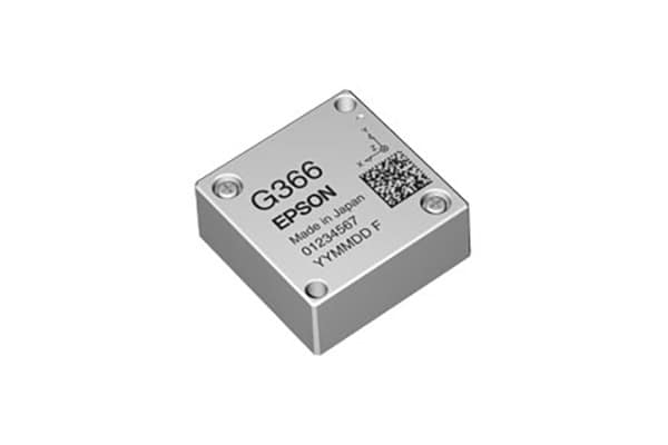
Within Epson’s compact IMU range, the M-G366PDG and M-G370PDG support output rates of up to 2,000 samples per second.
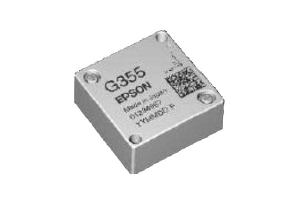
The M-G355QDG supports output rates of up to 400 samples per second.
These differences should be evaluated against the timing requirements of the intended control loop, alongside the relevant noise and bias specifications.
Temperature Performance
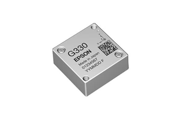
The Epson PDG series operates across a temperature range of −40 to +85 °C, making temperature compatibility an important consideration when selecting sensors for environments subject to significant thermal variation.
Epson IMUs are factory-calibrated over temperature. This calibration helps reduce the amount of additional temperature calibration required during system integration.
However, temperature-related errors must still be considered when evaluating performance under actual operating conditions.
Functional Safety Compliance
Some robotics and machinery applications require sensors suitable for safety-related functions.
The Epson M-G355QDG complies with IEC 61508 Safety Integrity Level 1 (SIL 1), providing a functional safety option within the company’s compact IMU range.
The device also shares the compact footprint of the M-G366PDG, which may be relevant when assessing mechanical integration requirements.
Physical Size and Weight
Space and weight restrictions are particularly important in compact robotic systems, drones and embedded navigation assemblies.
The Epson M-G330PDG, M-G366PDG and M-G370PDG share a 24 × 24 × 10 mm footprint and weigh approximately 10 g.
Their common physical dimensions allow engineers to move between these PDG performance levels without requiring a new board layout.
Comparing Epson Six-Axis IMU Models
Epson’s IMU range includes compact UART/SPI modules and externally housed sensors with industrial communication interfaces.
All the models listed below provide six-axis measurement capability and digital output, but their gyroscope performance, interfaces and physical configurations differ.
The values shown are typical specifications from Epson data sheets.

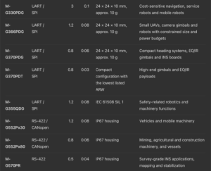
For the M-G552 series, the Px30 and Px80 designations cover the RS-422 (PR) and CANopen (PC) variants.
The comparison illustrates why an IMU should not be selected on a single specification alone.
For example, the M-G370PDT has a typical ARW of 0.03 °/√h, compared with 0.06 °/√h for the M-G370PDG, while both models have a stated bias instability of 0.8 °/h.
The M-G570PR provides a lower listed bias instability of 0.5 °/h, together with an RS-422 interface and IP67 housing, making it a candidate for different installation and navigation requirements.
Similarly, the M-G355QDG shares the M-G366PDG’s typical bias instability and ARW values of 1.2 °/h and 0.08 °/√h, respectively, but adds IEC 61508 SIL 1 compliance for applications involving safety-related functions.
These distinctions demonstrate the importance of evaluating performance characteristics alongside physical integration, interface compatibility and application-specific requirements.
Validating IMU Selection Through Application Testing
Published sensor specifications provide a starting point for selecting an IMU, but they do not fully represent the operating conditions of an integrated system.
The relative importance of gyroscope noise, bias instability, output rate and latency depends on how the sensor measurements are used. Environmental effects, mounting arrangements and external aiding sources can also influence overall performance.
Testing candidate devices within the intended system therefore provides a more representative basis for comparison than relying on data sheet values alone.
AMCORIS makes Epson evaluation kits available as free loans for qualified projects, allowing engineers to compare IMU models using their own measurement data and operating configurations.
A practical selection process begins by identifying whether stabilization, navigation, motion control or monitoring is the primary requirement. Gyroscope ARW and bias instability can then be compared against the relevant performance needs, followed by interface, housing, temperature, output rate, size and functional safety considerations.
Evaluating the resulting shortlist under representative operating conditions helps determine which IMU configuration best matches the technical requirements of the application.
Read How to Choose the Right IMU on the AMCORIS website.