
In this article, Travis Neumann, Special Project Manager at Omnetics Connector Corporation, discusses how to design miniature connectors for rugged performance. In this instance, the discussion will be centered around a connector for use on an aircraft engine to monitor performance.
BACKGROUND

A new aircraft engine is being developed by a large manufacturer and as the technology has developed, they want in operation monitoring at several different stages of combustion inside the jet engine.
To accomplish this, they place a number of sensors at each stage to detect vibration due to loads inside the engine. Sensors must withstand extremely high temperatures and pressures as they are exposed to the combustion process at all times. Signals from the sensors are directed to a box or number of boxes located on the outside of the engine housing. This box does have some specific requirements. Temperature ranges here can be as low as -70C and up to 175C during operation, as the altitude and airspeed can have significant impact on what this connector experiences. Additionally, there is a sealing element as well where the outside environment is not allowed inside this box to prevent instrument damage or a slower, long term issue like corrosion from occurring. This means the box itself is going to need to be sealed such that water or debris ingress is not an issue over the life of the engine.
Once there’s an understanding of the operating environment, the next step is to understand the power and signal requirements. Power and signal needs are the main driver in determining the contacts and/or form factor of the connector solution.
DESIGN

We have a good understanding of the requirements, and we have contacts we can reach out to for further questions as well as feedback. With sealing the box being a major requirement the first step is to consider a panel mount connector or alternate solution. Panel mounts have an O-ring to seal the gap between the flange on the connector and the box or bulkhead it’s being mounted too. Temperature ranges such as this would benefit from a silicone, Fluorosilicone, or Viton O-ring. Those are good solutions to just get the job done, but heat cycling could lead to material degradation and ultimately leaks. A second option is to incorporate the connector into the box by welding. This welding will provide no opportunity for leak paths between the connector housing and the box making it a great long-term solution and one which the assembly house has used before. Material considerations for this type of sealing quickly rule out aluminum with plating as its not suitable for welding. Using raw aluminum housings would lead to oxidization, so the next viable housing material is stainless steel.
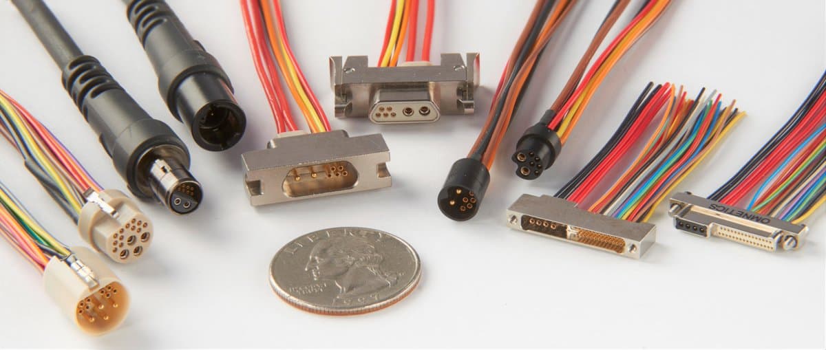
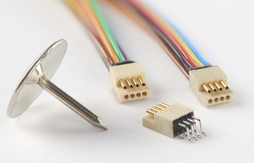
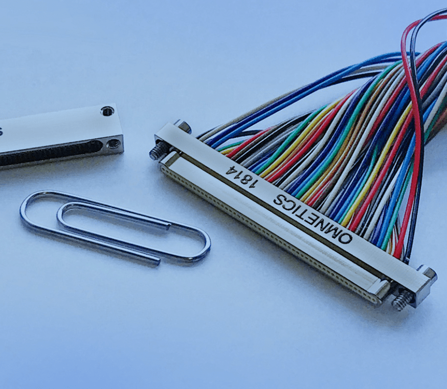
Once the housing material is determined, power and signal are the next discussion points on the list. There are up to six sensors going into the box with each sensor having power, ground and signal to manage. PCBs use power as well, so a few additional lines are required to settle on a 25 position Micro-D. No individual current draws greater than 3 Amps per line allows for use of a Micro-D connector. With many footprint options available in the Omnetics catalog, using the Mil-DTL 83513/10 pad layout provides ample clearance for the PCB designer to run traces from the connector to individual components.
While welding a stainless steel Mil-DTL 83513/10 to the box is possible, there are challenges using a standard design.

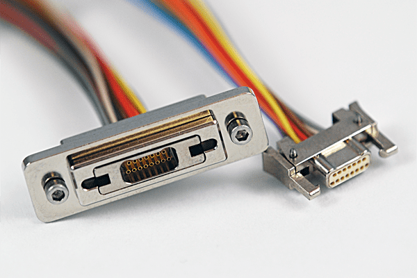
Flange thicknesses on 83513/10 Micro-D connectors are generally around .080” thick. Having this relatively thin flange requires the use of a butt joint/groove weld to the box. For strength in groove welds, the surfaces are typically prepped by chamfering for the appropriate level of joint penetration. This chamfer is not found in a standard Micro-D flange so additional processing to create a taper on the flange, or the box itself is needed. An easier solution is to changing the flange thickness which allows the assembler to use a fillet weld and eliminate the need of chamfering the box opening, connector flange, or both.
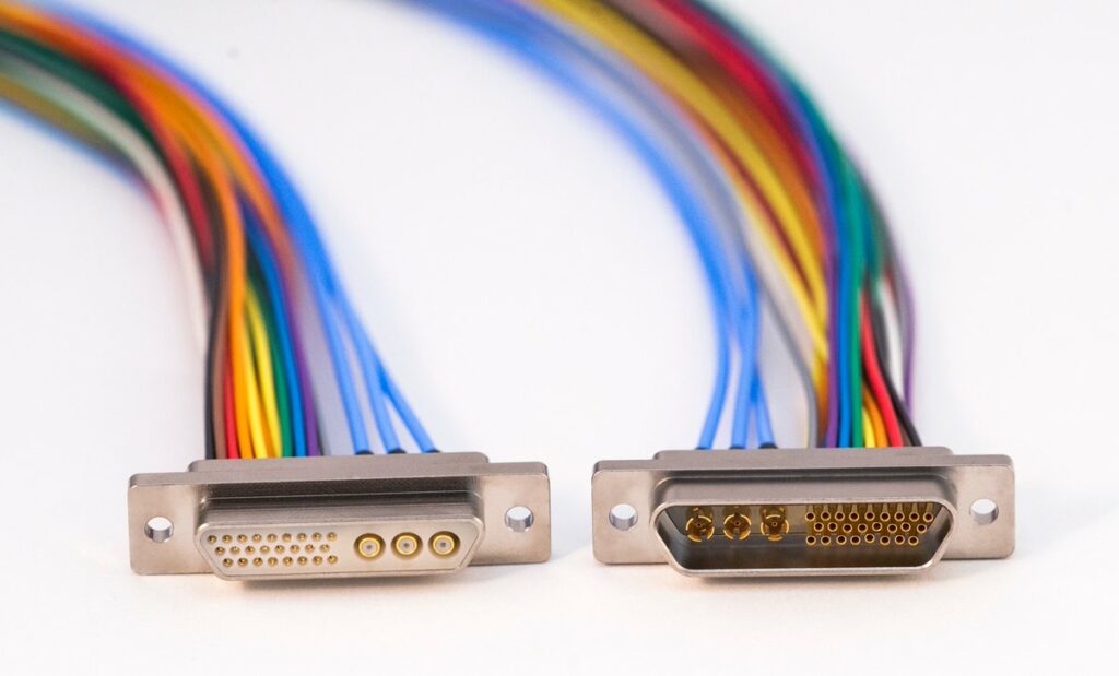
A second potential leak path using a standard Micro-D connector comes from the hardware on the front of the connector. Existing designs have several hardware options for customers, and as such, jackposts shown in the example above are clamped through the housing and organizer. To alleviate this leak path, a custom connector housing that seals the jackpost path and provides a flange for fillet welding will be the most manufacturable.

At this stage the remaining design challenge is fastening the connector flange to the organizer in a ruggedized manner. From earlier pictures, using hardware that clamps the two parts together is no longer and option as that created a leak path. Fastening the two, while allowing for a continuous weld path requires a creative design. After several iterations and testing and failures, a t-slot style fastener was settled on for use. This allows the connector parts to be assembled as they are currently on the standard Micro-D version with the exception of the fastening hardware. T slots are placed in a groove on the housing and slid into alignment. Once the locking collar is in place it draws the two parts together while assisting in alignment. All the features needed to perform the slot and locking are now contained inside the box to prevent creation of additional leak paths.

Jackpost hardware is now eliminated with this version of design with the threaded portion now being integrated into the connector shell. Risk of damaging threads on the box flange does exist, with the only real potential of occurrence during assembly in the construction phase.
CONCLUSION
Environmental requirements provide many factors to consider when designing for ruggedized performance. While there are many commonly used materials and designs in the marketplace, its by no means uncommon to require a custom solution that is based on a commercially available industry standard design. In those cases, it’s best to partner with a company and collaborate to develop solutions for your custom application.