
GNSS.store provides an overview of how different GNSS antenna configurations influence signal strength and receiver performance, focusing on the distinctions between passive, active, and smart antenna types.

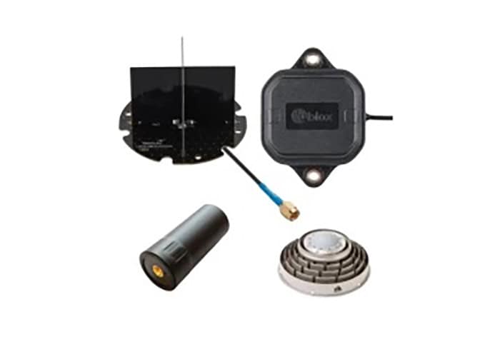
Passive antennas are the simplest form, operating without built-in amplification. Designs such as spiral or ceramic patch types are installed close to the receiver, commonly in mobile devices or trackers, to reduce signal loss through cables. Amplification occurs only within the receiver’s Radio Frequency (RF) stage, offering a cost-effective but limited-quality solution.
Since receiver microchips cannot integrate all required components, external filters are often used to block interference from nearby frequencies. GNSS signals are extremely weak, so unwanted signals such as television or satellite harmonics can disrupt reception. Surface Acoustic Wave (SAW) filters are widely used for this purpose, but because they cause signal weakness, they are typically combined with amplifiers.
When amplification is built into the antenna, the configuration becomes an active antenna. A standard layout follows antenna → amplifier → filter → amplifier. Active antennas produce stronger signals suitable for long cable runs, with gains up to 40 dB allowing the use of cables up to 100 meters. Power is supplied through the same coaxial cable. However, a higher gain does not always improve performance, as excess amplification increases noise. Signal-to-noise ratio remains the key performance measure.
Powering an active antenna through long cables can cause voltage drops, so many include a regulator to accept 3–5 V input. Monitoring supply current also allows automatic detection of short circuits or disconnections based on predefined current limits.
The development of smart antennas integrates both the receiver and antenna into a single enclosure, replacing coaxial cables with digital connections over twisted pair. Smart antennas function as compact receiver systems rather than standalone antennas and are used in most applications except precision timing.
To avoid such interference, the antenna and receiver ground planes must be separated, and no digital or high-frequency circuitry should be placed near the antenna section.
To find out more, visit GNNS.store’s website.